This page is about my LED project
Still not convinced that I'm great?
This isn't a school project or anything like that. It's personal.
About a month ago I was searching online for some graphical LCD displays for a possible project, but I did a little bit of digging and found this.
I don't know if you've ever hooked up several LEDs, but there is a limit where construction becomes sculpting; literally innovating the space given to accomplish a goal. It goes beyong logical circuitry and become illogical and unique.
Needless to say, I was inspired. I didn't know what I was going to do, but I knew it was going to involve a lot of LEDs and skills I didn't readily have.
Instead of going the route the person before me took, I picked up some of These. I lack the equipment to make custom PCBs.
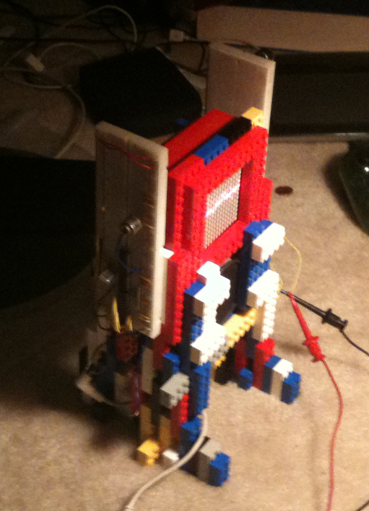
Anyway, I went to work conceiving a method of putting it all together. All of my ideas were still breadboard based and two dimensional. However, after getting my big-ass bucket of Legos from my parents house earlier in this week, I got a really awesome idea. It was probably the best moment of the project: build a case out of Legos.
So I did. I mounted the display that I assembled into a square Lego box with a hole on either side for wires. I prepped the circuitry, and built the case all while debugging the program and testing the leads. I didn't bother to count how many wires I've stripped in the past week (Nearing a thousand I'm sure). The thing was on the whole time and it was poetic watching it culminate.
It isn't 100%, but the case, major wiring and fundamental programming are working just fine. There's a bit of noise in the system, so mind the bump.
Parts list:
ATmega168 (1x)
LEDMS88O (4x)
74154 (2x)
7474 (2x)
7404 (3x)
some pots, resistors, capacitors, and a crystal oscillator
gobs of wire
Legos
This is the rear of the display. I left it open so you can peek inside. There are lots of wires. Anyway, this was my first obstacle. The LED matrix must be set up to have 32 leads. There were 64 that I had to wire together. It was a little frustrating at first, but I found a rythme.
The bottom side of the device. This is where I decided to interface with each section. It is the central node that makes an easy interface with the orderless wires of the display and the side panels aswell as where I keep the speaker and 1/8" jack for audio. It will also serve as the place for the power supply as soon as the electronics store opens at 9. >_>
This is the left side. It controls the columns of the array. The circuitry here includes a 555 timer, a 4 bit counter, a 4-16 line demultiplexer and 16 inverter gates. All it does is count. Eventually, I will leave that up to the microcontroller, but for now it works fine.
A quarter of the wiring; twice the headache. This panel holds my microcontroller (ATmega168). Like the other side, it has a 74154(demultiplexer), but it doesn't have any inverters. That's because this panel interfaces with the rows of the array, and all of the rows are cathodes of the LEDs. "Elementery," you say? Yah, bite me...
This is the front. Take a moment to admire the Legos. They were a major influence.
This is the back. More Legos.
Thanks for reading!